
Using Frequency Converters with TWISTER
Terms:
CCU: Compact Up-Converter (VDI-737 CC)
CCD: Compact Down-Converter (VDI-737 CC)
AWG: M8195A - Arbitrary Waveform Generator
PSG: E8257D - Analog Signal Generator (x2)
DSO: DSOV254A - Digital Storage Oscilloscope
Important notes about operating the frequency converters:
- Wear a grounding strap when handling. The IF input of the CCU unit (and the rest of the devices to a lesser extent) are extremely ESD sensitive.
- Disable AWG and PSG outputs before connecting to input of CCU/CCD. Applying input signal to the devices in the wrong order or while they are powered off can result in irreparable damage.
Tips on calculating appropriate power output values
- See the datasheet for the particular CCU/CCD units you are using. The maximum
allowable input power value varies by device. The limit also differs for the LO and IF
ports. - Remember to account for loss caused by the cables you are using. This should be listed
on the cable spec-sheet, or it can be easily measured using the VNA or DSO. - The cable loss varies by frequency. Make sure you calculate the correct loss for the
frequency a particular cable will see. - To calculate correct signal amplitude for the AWG, remember to convert AWG output
voltage to RMS. The following formula can be used:

- Make sure you do not overload the RF input of the CCD (this isn’t likely to be a concern
if the THz signal is not being amplified).
Startup Procedure
Start with all cables disconnected.
- Calculate desired frequency/power output for PSG.
- see Tips on calculating appropriate power output values. - Set PSG output frequency and amplitude using the appropriately labeled buttons.
- Disable the outputs of the PSGs.
- The outputs should be disabled by default, but you should double check that the icon on screen says 'RF OFF'
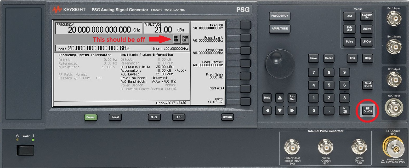
- The outputs should be disabled by default, but you should double check that the icon on screen says 'RF OFF'
- Calculate and set desired output voltage for AWG.
- see Tips on calculating appropriate power output values.
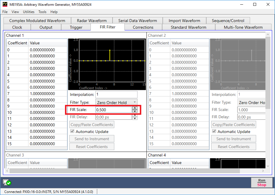
- Tip: set maximum amplitude in Output tab and then adjust output level by changing FIR Scale value in the FIR Filter tab.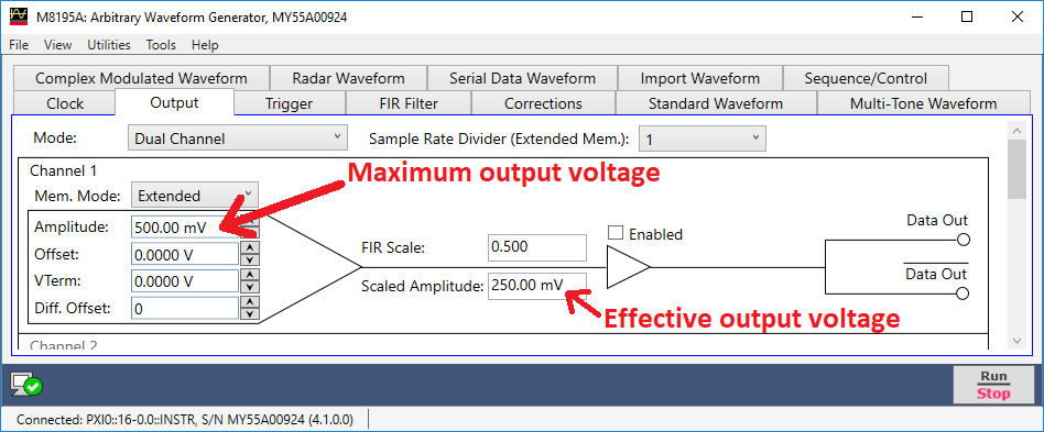
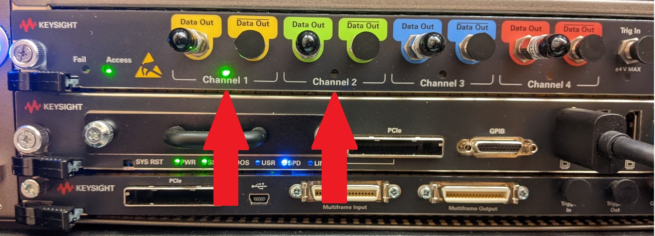
- Disable the outputs of the AWG (uncheck ‘Enabled’ for each available channel in the
Output tab). The channel LEDs should be unlit.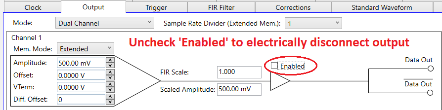
- Double check that the outputs for each device are disabled.
- When in doubt, shut the signal sources off. Once you have made all the connections,
they should boot up in a safe state. - Make sure the CCU/CCD are powered off (unplugged).
- Connect Devices (see document on Proper use of high frequency coaxial cables)
a. PSG output to CCU/CCD LO inputs.
b. AWG output to CCU IF input.
c. CCD IF output to DSO input.Connect power to the CCU/CCD. - Connect power to the CCU/CCD.
- Verify that PSG and AWG output levels are within the safe operating range that you calculated.
- Enable PSG outputs.
- Enable AWG outputs.
Shutdown Procedure
It is important that you turn off and disconnect devices in the correct order to avoid damaging equipment.
- Disable AWG output.
- Disable PSG output.
- Disconnect CCU/CCD power supplies.
- Power off AWG, PSG, DSO.
- Replace the dust covers and/or protective tape on the CCU and CCD outputs.
- Disconnect cables if system is to be stored.